10+ vco block diagram
ESP8266 offers a complete and self-contained Wi-Fi networking solution allowing it to either. A block diagram of the Si5351 programmable clock IC is shown in Figure 1.
How Does A Voltage Controlled Oscillator Vco Work Quora
10 is a diagram analogous to FIG.

. 130 ppm frequency 10 kHz 50 ppm frequency 10 kHz Amplitude range 20 mV pp to 5 V pp into Hi-Z. But in terms of phase its a linear block F Div F VCO N Div Z t 1 F. When in sleep.
Know the inspection requirements for. Injection Lock Oscillator with PLL and a NB3N502 MEMS Oscillators - SiT8008SiT8208SiT8209. The driver is capable of 03 A min.
An example of this is the case where the parallel resonance frequency of the crystal is decreased or increased by adding a capacitor or an inductor across the crystal respectively. The block diagram of a PLL operating as a frequency synthesizer is shown in Figure 1 8. The controller enables the receive VCO when the frame count reaches this value.
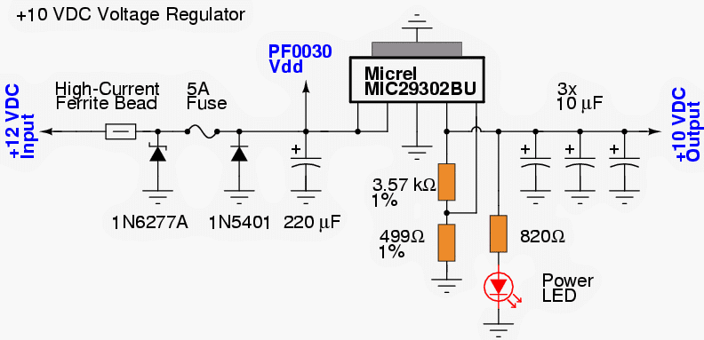
This chip effectively includes 6 internal op-amps that the designer can use and a power supply subsystem. Functional block diagram. A 100 MHz Reference Frequency Add-On DIL-28 Formfactor.
Intermediate frequency signals Z1. The user needs to make sure that the RF device is in a state from where this operation is valid. Each channel includes a local oscillator 16 VCO.
Know basic crane terminology and definitions. Know current federal regulations and industry standards including but not limited to ASME B305 B3010 OSHA 1910180 1926 Subpart CC. ESP8266 80211bgn Smart Device.
The PLL structure consists of a low-power linear VCO and two. A universal VCO Board - MC100EL1648DG and PGA-103 A universal XCOPLL Board - NB3N501502511. 9 a part of evaluation unit 26 is shown as a block diagram.
Injection Lock Oscillator with PLL and a NB3N502 MEMS Oscillators - SiT8008SiT8208SiT8209. 001 01 1 10 100-80-40 0 40 Normalized Frequency Magnitude dB 00101 1. Block Diagram Data Sheet 10 Rev.
Pin2 Modulation Modification - Chorus. Adrf6701 adrf670x family clock drivers. An electronic oscillator is an electronic circuit that produces a periodic oscillating electronic signal often a sine wave or a square wave or a triangle wave.
10 - 90 or 10 ns minimum pulse whichever is larger. A 100 MHz Reference Frequency Source locked to 10 MHz. Know functions and limitations of cranes and attachments.
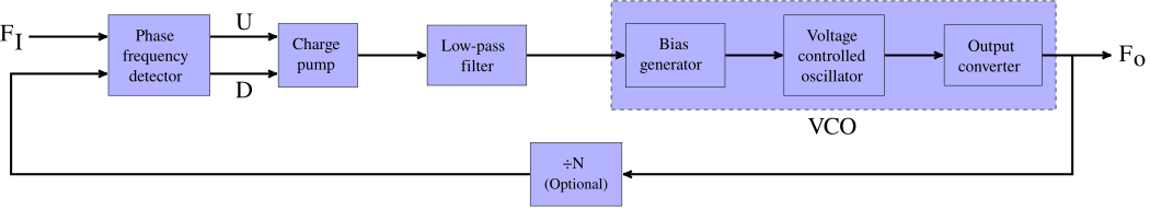
Introduction The Si5351 is a highly flexible and configurable clock generator and VCXO. It consists of a reference oscillator OSC a phasefrequency detector PFD a charge pump CP a loop filter LF a voltage-controlled oscillator VCO and two frequency dividers FDs. A 100 MHz Reference Frequency Source locked to 10 MHz.
2 Technology Overview. The pin is actively pulled to. The typical operating range of the crystal oscillators is from 40 KHz to 100 MHz wherein the low frequency oscillators are designed using OpAmps while the high frequency.
Iq modulators with pll and vco. Or less than 05mW DTIM10 to stay. Typical system block diagram N.
The PLL is a feedback loop that wh en in lock forces. Ad9516 ad951x family. 5 for the near-field mode and it illustrates a modified example embodiment of the radar sensor according to the.
This block diagram could be redrawn in a more logical and simpler way. A 100 MHz Reference Frequency Add-On DIL-28 Formfactor. Typical system block diagram L6599 636 3 Typical system block diagram Figure 3.
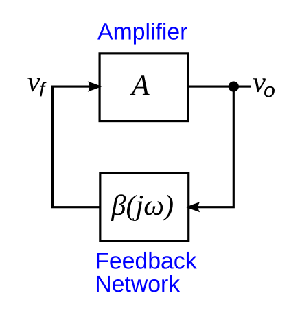
Voltage controlled oscillator. 4 CD4046B Phase-Locked Loop. Block diagram of a PLL.
This voltage drives an external voltage-controlled oscillator VCO to increase or decrease the output frequency so as to drive the PFDs average output towards zero. Source and 08 A min. PLL VCO DDS Oscillators.
Data 2 pre mod. 10 2017-02-02 2 Block Diagram Figure 1 Block Diagram TLE9879QXA40 CP1L TEST DEBUG INTERFACE ARM CORTEX-M3 FLASH SRAM ROM Multilayer AHB Matrix PBA0 MOSFET Driver PMU Power VDDC VDDEXT LIN. Minimum pulse time applies to both on and off time so maximum duty cycle will reduce at higher frequencies to maintain 10 ns off time.
10 mV pp to 25 V pp into 50 Ω Duty cycle range. The axi_ad9361 cores architecture contains. Name Function 11 LVG Low-side gate-drive output.
The VCO may have to be enabled before data can be received. Sink peak current to drive the lower MOSFET of the half-bridge leg. Oscillators convert direct current DC from a power supply to an alternating current AC signal.
5 P a g e Espressif Systems Oc t 12 20 13. PLL VCO DDS Oscillators. Phase Locked Loop Block Diagram ÖN Ref Div Loop Filter VCO Phase Locked Loops PLL are ubiquitous circuits used in.
In the example shown an ADF4xxx synthesizer is used with an external filter and VCO. They are widely used in many electronic devices ranging from simplest clock generators to digital instruments like. Fifo hb1 hb2 hb3 nco and mod f.
A universal VCO Board - MC100EL1648DG and PGA-103 A universal XCOPLL Board - NB3N501502511. Multichip synchronization d15pd15n d0pd0n. Manually Generating an Si5351 Register Map for 10-MSOP and 20-QFN Devices 1.
Technical Brief SWRA029 FractionalInteger-N PLL Basics 5 The problems associated with operating a wireless communications system have become especially acute in the last few years with the advance of cellular telephony and. This is the voltage used as a virtual ground inside the PT2399 and also as a reference voltage for the VCO circuit. Connected to the access point.
A Versatile Building Block for Micropower Digital and Analog Applications 3 CD4046B PLL Technical Description Figure 2 shows a block diagram of the CD4046B which has been implemented on a single monolithic integrated circuit. Frequency is scaled by the use of counters.
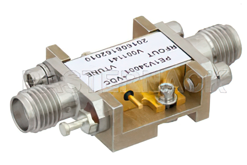
Voltage Controlled Oscillator Vco 5 Ghz To 10 Ghz Phase Noise Of 93 Dbc Hz Hi

Block Diagrams Of A Coherent Ook Receiver With The Injection Locking Download Scientific Diagram
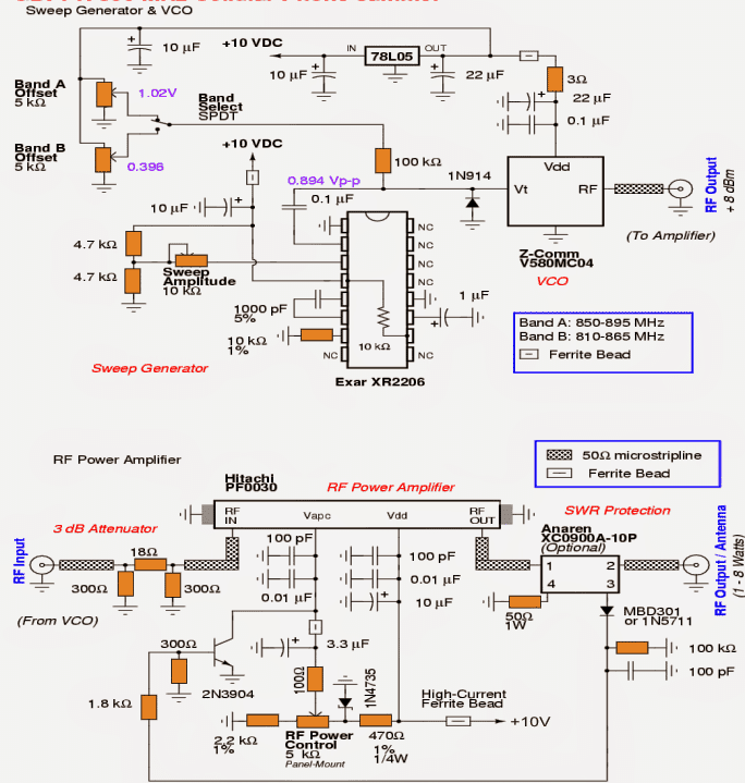
Simple Cellphone Jammer Circuit Homemade Circuit Projects

Simple Vco Using Schmitt Trigger Using 74hc14 Electronics Circuit Basic Electronic Circuits Circuit

Costas Loop Wikiwand
How Does Vco In Pll In A Computer Processor Work Quora
Electronic Oscillator Wikiwand

Voltage Controlled Oscillator Vco Circuit Voltage Controlled Oscillator Electronic Circuit Projects Circuit
How Does A Voltage Controlled Oscillator Vco Work Quora
How Does Vco In Pll In A Computer Processor Work Quora

Lmc567cn Lmc567cn Original Original Supply Us 0 50 0 50 Audio Ics Ns National Semiconductor Seekic Com
Phase Locked Loop Wikiwand
Simple Cellphone Jammer Circuit Homemade Circuit Projects

Tracking Range Of Pll And Frequency Range Of Vco Versus Power Supply Download Scientific Diagram

Ne566 Function Generator Voltage Controlled Oscillator Vco Circuit Voltage Controlled Oscillator Function Generator Linear Function
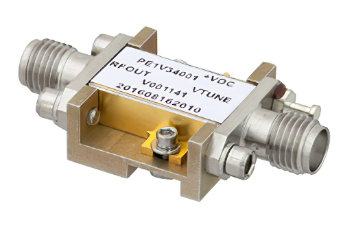
Voltage Controlled Oscillator Vco 5 Ghz To 10 Ghz Phase Noise Of 93 Dbc Hz Hi Rel Hermetic And Sma
Frequency Synthesizer Wikiwand